
Are You Overlooking a Critical Factor in Steel Beam Design?
The Impact of Splice Stiffness
As structural engineers, we’re constantly striving for accuracy and efficiency in our designs. We rely on sophisticated software, robust materials like S275 steel, and well-established codes of practice. But are we sometimes missing a subtle yet significant element that could compromise the performance of our steel structures? The answer, surprisingly, lies in how we handle splice connections.
The Splice Connection Blind Spot
When designing steel beams that span beyond standard lengths (typically over 6 meters), we inevitably encounter the need for splice connections. These connections, usually bolted, allow us to transport and erect longer beam sections. Here’s the problem: many structural engineers primarily design these splices for shear and moment capacity, ensuring they can adequately resist the applied forces. While this is undoubtedly crucial, it often overlooks the connection’s rotational stiffness.
That’s right – we’re not always paying attention to how rigidly these splices hold the beam together.
What happens when we ignore this rotational stiffness? Well, we design the splice only for shear and moment capacity, but the splice stiffness is low, meaning it’s not as rigid as the beam members. In this scenario, the beam deflects more than we expect.
The Continuous Beam Assumption: A Dangerous Simplification
Design software often models beams as perfectly continuous elements. This is a convenient simplification, but it doesn’t reflect reality when splices are present. A splice, by its very nature, introduces a degree of flexibility. The degree of flexibility will affect deflection of the beams. If this flexibility isn’t accounted for, our software predictions for deflection can be significantly underestimated. And if we are not designing the splices properly for stiffness requirements, then the result will affect cost and safety of the beams too.
Case Study: An 8-Meter S275 Beam
To illustrate this point, consider a recent study conducted on an 8-meter steel beam (254x254x73UC) made from S275 steel. The beam was subjected to a uniformly distributed dead load of 4.5 kN/m and a live load of 5 kN/m, representing typical service conditions.
Initial Analysis: When the beam was modeled as a continuous 8-meter section in Robot Structural Analysis, the deflection under Serviceability Limit State (SLS) conditions was predicted to be 21 mm.
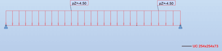
Figure 01: Dead loads of the 8m beam
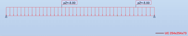
Figure 02: Live loads of the 8m beam
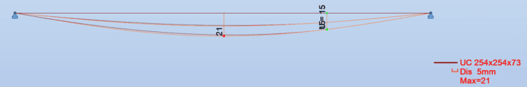
Figure 03: Deflection(SLS) of the 8m beam
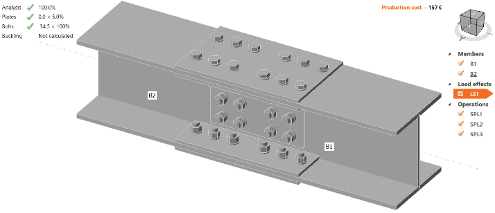
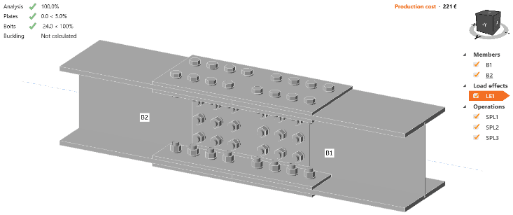
The Splice Connection Factor: However, when a splice connection was introduced at the 6-meter mark and modeled using IDEA StatiCa, a different picture emerged. By varying the splice connection design, the study explored the relationship between connection utilization, rotational stiffness, and beam deflection.
The Data Speaks Volumes: Utilization vs. Stiffness
Results
| Design no | Splice design | Rotational stiffness/ MNm/rad | Splice connection utilization | Deflection – SLS mm |
|---|---|---|---|---|
| 01 |

| 4.1 | 94.9% | 36 |
| 02 |

| 4.7 | 83.4 | 34 |
| 03 |

| 5.3 | 74.1 | 33 |
| 04 |

| 7.5 | 59.3% | 29 |
| 05 |

| 8.3 | 46.0% | 28 |
| 06 |
| 12.4 | 34.5 | 26 |
| 07 |
| 18.5 | 24.0% | 24 |
The results were compelling:
Design Utilization vs. Deflection (SLS): As you can see in the graph below (Figure 1), the higher the design utilization of the splice connection, the greater the deflection. A splice pushed close to its capacity (high utilization) is inherently less stiff, leading to increased deflection.
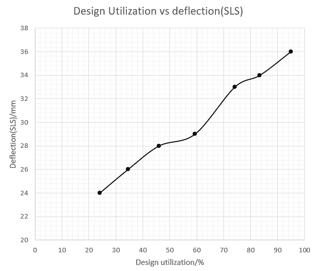
Figure 04: Design Utilization vs. Deflection (SLS
Rotational Stiffness vs. Deflection (SLS): Conversely, as shown in Figure 2, the greater the rotational stiffness of the splice connection, the lower the deflection. A stiffer connection behaves more like a continuous beam, minimizing deflection.
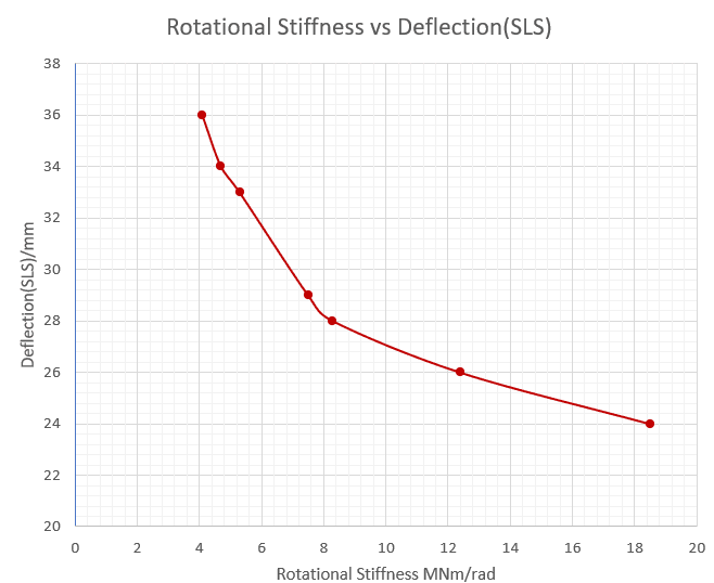
Figure 05:Rotational Stiffness vs. Deflection (SLS)
In our study, we observed deflections increasing from 24mm to 36mm when the design utilization of the splice increased. Similarly, deflection decreased from 36mm to 24mm as the rotational stiffness was increased in the splice.
The Real-World Consequences
Ignoring rotational stiffness can have significant consequences:
Underestimated Deflections: Our designs might predict acceptable deflections that are, in reality, much larger.
Serviceability Issues: Excessive deflection can lead to cracked finishes, malfunctioning doors and windows, and a general perception of structural inadequacy.
Potential Structural Distress: In extreme cases, underestimating deflection could contribute to structural instability.
Time to Change Our Approach?
Structural engineers need to start incorporating rotational stiffness into their splice connection designs:
Software Integration: Leverage software like IDEA StatiCa to accurately model and analyze splice connection behavior, capturing both strength and stiffness characteristics.
Design Guidelines: Advocate for the inclusion of more comprehensive guidance on splice connection design in relevant codes and standards.
A Holistic View: Think beyond simple force resistance and consider the overall stiffness of the connection as an integral part of the structural system.
By acknowledging and addressing the impact of splice connection rigidity, we can ensure more accurate, reliable, and robust steel structures. Let’s bridge the gap between theory and reality, one splice at a time.

Strucad Engineering is committed to delivering precision, innovation, and reliability in every structural solution. With a passion for excellence, we engineer structures that stand strong for generations. Connect with us to build the future together.
Information
Location
-
30/4, 4th Lane, Obahena Road, Madiwela, Kotte
Sri Lanka
Newsletter
© 2024 – 2025 | Alrights reserved by STRUCAD ENGINEERING | CMS Provider Epceylon